|
1
|
- Post Mortem & Memory Requirements
- Design Considerations 2:
|
|
2
|
- POST-MORTEM ANALYSIS (chap. 6.9
& 9.8)
- In case of a beam dump, the BLM system should help answering the
following questions:
- is the beam dumping clean or were there unexpected losses around the
machine?
- what is the cause of the dump action: beam losses triggering the BLM or
internal magnet quench protection interlocks? Other machine interlocks
without prior beam losses?
- The signals of all monitors should be buffered for the last 100 - 1000
turns, such that they can be read out and analysed after a beam-dump. In
addition, the average rates of all monitors should be easily available
for time scales of a few seconds and 10 minutes before a beam-dump.
|
|
3
|
- We can sub-divide the various LHC systems into the following categories:
- Triggered systems (via specific
external event) :
- • beam instrumentation
- • power converter system
- • RF system
- • …
- Self-triggered systems :
- • quench protection system
- • beam dump system
- • power converter system (on faults ?)
- • …
- Non-triggered systems :
- • Interlock system, BIC & PIC
|
|
4
|
- Transient
- System required to record fast signals and freeze on trigger
- Logging
- System required to continuously (on time or on change) record slow or
infrequent changes
- Alarms
- System required to send fault events to the Central Alarm Server,
(CAS).
- External Trigger
- System required to respond to general PM trigger
- Internal Trigger
- System required to autonomously record all protection actions
- Date
- Operational for Sector Test or Beam Commissioning
|
|
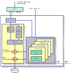
5
|
- The correct functioning of all these systems is required to ensure
proper protection of equipment.
- (Beam Dumping System, Beam Loss
Monitors, Energy Extraction Switches, Quench Protection, etc)
- Beam Loss Monitors:
- They are included here as a critical part of the machine protection
system, their status should be logged.
- Beam loss information should
be recorded
- at 100 Hz, depth 20s
- or
- Beam Loss 2000 channels * 100Hz * 20s = 4E6 values
- (Note: Beam Position 2000 channels * 1000 T = 2 E6 values)
|
|
6
|
- Observation Time-Windows
- Adding newest data
- Subtracting oldest data
- Capacity of FIFO
- Th & W table values depending on:
- Beam Energy
- Ion. Chamber Position
- Time-Window
- Read 2 values from a table of 576 values
- Comparisons on chip
- 96 times in parallel (6 TimeWind.*16 Ion)
|
|
7
|
- Acquisition every 40μs:
- 25 KHz
- 16 Ion. Chambers per Card.
- 8 bit values
- 1024K x 36bit SRAM can hold 10.24s of data
- Write Clock = 400 KHz & Read Clock = 2.4 MHz
- 10 seconds need 250K x 8bit per Ion. Chamber.
- Acquisition every 90μs (1 turn):
- 11 KHz
- 16 Ion. Chambers per Card.
- 8 bit values
- 1024K x 36bit SRAM can hold 23.04s of data
- Write Clock = 180 KHz & Read Clock = 1.1 MHz
- 10 seconds need 110K x 8bit per Ion. Chamber.
- *Note that 2 SRAMs can be available to keep the data under manipulation
and 1 SRAM for PM.
|
|
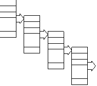
8
|
- When A has been filled with 10 acquisition values, the sum of them is
appended as a value to B.
- When B has been filled with 10 values, the sum of them is appended as a
value to C, and so on.
- In that way sums of tenths, hundreds, thousands, millions, … of values
are created and kept.
|
|
9
|
|
|
10
|
|
 Notes
Notes