|
1
|
- Design Considerations of Digital Parts.
- Internal Review
|
|
2
|
- Tunnel
- CFC Digital Part
- Implementation of tunnel FPGA
- Frameword for Transmission
- Communication Link Options
- GOL Transmitter
- Identification of cards
- Summary
|
|
3
|
- Design criteria
- Radiation Tolerant Devices available:
- Actel SX/A family ($40)
- Xilinx QPRO family (~20x more)
- Not very complicated digital part but
- Triple module redundancy
- Medium device
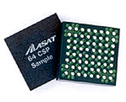
- PQFP vs. BGA package
- Will give simpler and cheaper PCB
- Make use of socket
|
|
4
|
- Production of CRC-32 error detection redundant information
- All single-bit errors.
- All double-bit errors.
- Any odd number of error.
- Any burst error with a length
less than the length of CRC.
- For longer bursts Pr =
1.16415*10-10 probability of undetected error.
- Tunnel PCB arrangement
- 8x12bit ADC in parallel + control signals,
- 8 Counter inputs, etc.
- To be done:
- Counters
- Registers for ADC data
- Multiplexing of all information
|
|
5
|
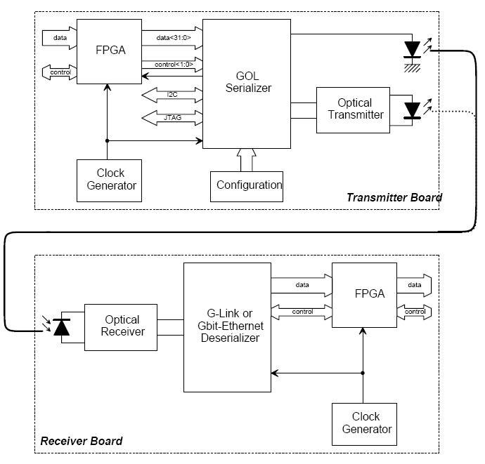
- Formatting of the frameword for transmission (256 bits)
- Transmission of frameword every 40μs.
- The rate must be high enough to minimise the total latency of the
system .
- Redundant optical link
- In order to increase the reliability of the system.
|
|
6
|
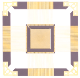
- Use the Gigabit Optical Link (GOL) chip
- High-speed transmitter ASIC (at 800 or 1600 Mbps).
- Radiation tolerant layout (in 0.25 mm CMOS technology).
- Also includes:
- Analogue parts needed to drive the laser.
- Algorithm running that corrects SEU.
- 8b/10b encoding.
- 16 or 32 bit input.
- Error reporting (SEU, loss of synchronisation,..)
- More Advantages:
- Very low cost (50CHF for both ASIC & Laser).
- Already tested and functional.
- Independent system.
- Allows later improvement of design.
- Build a custom communication link.
|
|
7
|
|
|
8
|
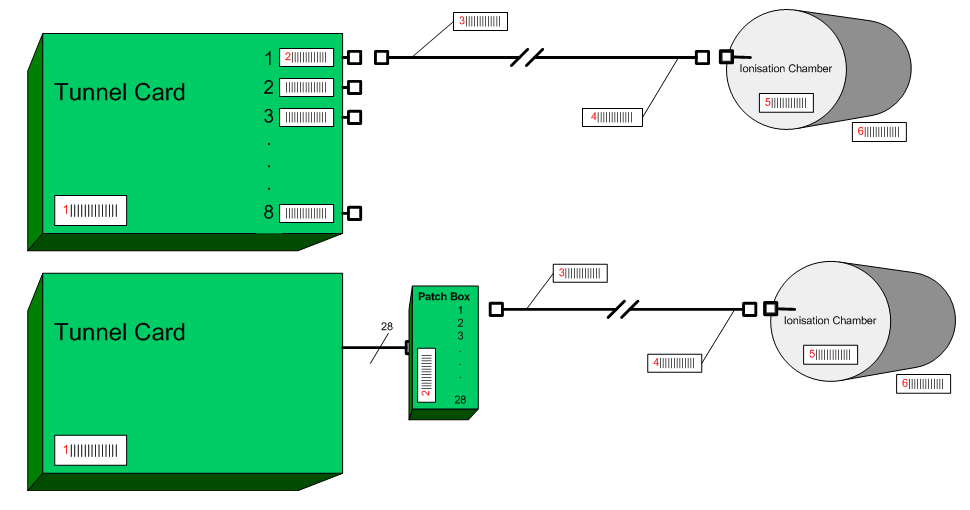
- Identification of cards
- Barcode system for installation and indexing of cards, cables,
detectors, position
- Digital ID of cards on every transmission/check
- Serial number for each frame transmitted
|
|
9
|
- Tunnel FPGA will be Actel’s family SX/A with 208 pin sitting on a
socket.
- Of great importance is to decide the communication link (will dictate
the whole of the tunnel digital implementation and the rest of the
surface part).
|
 Notes
Notes